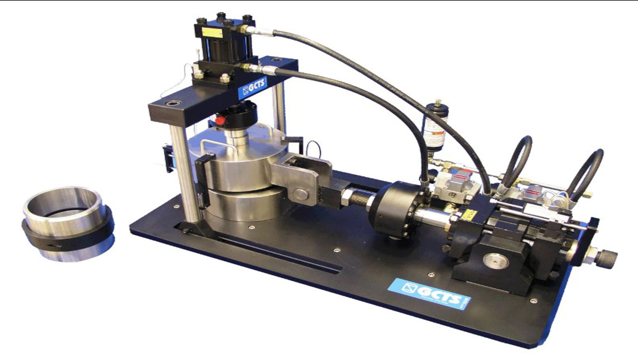
To determine shear strength of a soil sample by Direct shear test, first, you should know some basic things.
So Let’s start with the basics.
Shear Strength of Soil.
The shear strength of soil is the resistance to deformation by continuous shear displacement of soil particles or upon the action of a tangential (shear) stress.
The shear strength of a soil is basically made up of;
1. The structural resistance to displacement of the soil because of the interlocking of the soil particles.
2. The frictional resistance to the translocation between the individual soil particles at their contact points, and
3. Cohesion (adhesion) between the surfaces of the soil particles.
Determination of Shear Strength of Soil.
The shear strength of soil is usually determined experimentally by one of the following methods.
1. Direct Shear Test.
2. Laterally Confined compression test, also known as the triaxial compression test.
3. Unconfined compression test.
In this article, our main focus will be on Direct Shear Test.
Direct Shear Test.
The purpose of the direct shear test of soil is to obtain its ultimate shear resistance, its angle of internal friction, its cohesion, and its shear stress deformation characteristics.
This information is necessary for substructure analyses, in determining the bearing capacity of the soil, in stability calculations of earth slopes, in pile driving, and other earthworks.
Object.
To familiarize the young Engineers with a procedure for rapidly estimating the shear strength Parameters (angle of friction and cohesion) of a soil sample.
You must understand the nature of shearing resistance in order to analyze the soil stability problems such as;
Bearing capacity, slope stability and lateral pressure on the earth retaining structures.
Standard:
1. AASHTO T236-90
2. ASTM D3080-90
3. BS 1377: Part 4.
Apparatus:
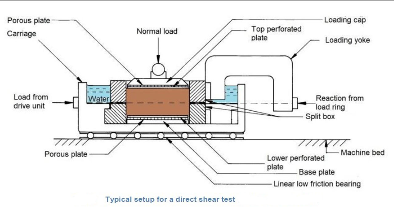
1. Shear box equipment consisting of:
a) Shear box, 60 mm square & 50 mm deep so that sample of size 60 x 60 x 20 mm may be tested.
The box should be divided into two parts horizontally, with suitable spacing screws.
b) Container for the shear box.
c) Grid plates two pairs, one pair plain and another pair perforated.
d) Porous stones, one pair 6 mm thick.
e) Base plate with cross grooves on its top face to fit into the shear box.
f) Loading pad with a steel ball on its top.
2. Loading frame, to distribute the load from the yoke over the specimen normal to the shear plane.
3. Set of weights for the normal load.
4. Proving ring with dial gauge accurate to 0.002 mm to measure the shear force.
5. Micrometer dial gauge to measure horizontally & vertically displacement during shear.
6. Spatula, straight edge, sample trimmer.
7. Stop watch.
Sample Preparation.
If an undisturbed sample is used, it should be large enough to provide a minimum of three identical specimens.
Prepare the specimens so that the moisture loss is negligible.
Trim oversize specimens to the inside diameter of the direct shear device and to the length of the trimmer.
Extreme care shall be taken in preparing undisturbed specimens of sensitive soils to prevent disturbance of their natural structure.
Determine the initial mass of the specimen for subsequent use in determining initial moisture content.
If specimens of compacted soil are used, they shall be compacted to the desired moisture density conditions.
 Procedure
1. Prepare at least three samples with the help of sample trimmer.
2. Fix the upper part of the shear box to the lower part in saturation container and insert the lower block.
3. Carefully place the sample in the shear box and insert the upper loading block in place.
4. Place the box in its proper position on the shearing machine.
5. Mount the loading yoke on the steel ball, placed on the loading block, and hang 10 kg normal load.
6. Apply shear force so that the loading knob just touches the top portion of the shear box and a very small load is applied.
7. Remove the fixing screws (pins) holding the upper and lower part of the box together,
and raise the upper half box slightly larger than the largest soil particles in the sample by advancing the spacing screws.
Then back off the spacing screws so that they clear the bottom half of the box.
8. Adjust the proving (load) ring dial to read zero and apply the shear force and shear the sample slowly at a constant rate until the maximum shear force is reached at the failure of the sample.
9. Repeat the test on identical samples under increasing normal loads of 20, 30, 40 kg, etc.
10. Plot the failure envelope between normal stress as abscissa & shear stress as ordinate using the same scale.
Measure the slope of the line to read the angle of internal friction (φ) and the intercept with the ordinate as cohesion, C.
Observation and Calculations.
Sample Size. _______________.
Area of Samples (A). _________________.
Weight of Loading Block + Steel Ball. ____________.
Proving Ring Constant. ___________.
| Sr. No. | P = Normal Load (Kg) | P/A = Normal Stress (Kg/sq.cm) | Dial Reading | S = Shear Forces (Kg) | S/A = Shear Stress (Kg/sq.cm) |
|---|---|---|---|---|---|
| 1 | |||||
| 2 | |||||
| 3 |
Result.
The shear strength parameters of a given soil sample are:
C = _________ N/cm2.
φ = _________.
Precautions.
If the test is performed regarding saturated condition then,
1. Put porous stone at the top and bottom of the shear box with grippers before starting the test.
2. After placing the shear box cart in the machine, fill the cart fully with water and allow the saturation of sample.
3. Remaining procedure is the same as described above.
Read More: Standard Penetration Test (SPT) of Soil – Procedure, Tools, Precautions.

 Procedure
Thank you for pointing out that the shear strength is based on the cohesion between the surfaces of the soil particles. This seems like something you would want to make sure you were educated on. Hopefully, people look into finding the right company to test this.
as per ABOVE ARTICLE we are know the test very help full me
Thank you very much to discuss this in elaborated and very nice.
what should be the time interval for the readings?