Pipe System Design.
The design of a pipe system requires a detailed map of the city, showing contours (or all controlling elevations) and the location of present and future streets and lots.
After studying the topography and selecting the location of distribution reservoirs, the city may be divided into districts, each to be served by a separate distribution system.
The probable maximum use (allowing for fire and future growth) for each sub-area of the city must be estimated.
A skeleton system of supply mains leading from a distribution reservoir is assumed.
These supply mains must be large enough to deliver the expected requirements with adequate pressure.
The Hardy Cross method is used to determine the discharge and head loss in each pipe of the network.
The effect of the flow in auxiliary mains is neglected at first but may be accounted for later.
Flow in the supply-main network is analyzed for fire use located in several different areas of the district to check the adequacy of the system under various patterns of withdrawal.
In selecting supply mains, possible future capacity requirements should be considered.
It may prove much wiser to anticipate future requirements than to replace the main with a larger one at some future date.
After the supply-main network is selected, distribution mains are added to the system.
The hydraulic computations can be only approximate since all factors affecting the flow cannot possibly be accounted for.
Watch the Video Below for Better Understanding.
Minor distribution mains which serve fire hydrants should be at least 6 inches in diameter in residential areas and 8 or 10 inches in diameter in high-value districts.
Street mains serving only domestic needs are normally 2 or 4 inches of pipe.
Read More: A Detailed Guide on Reciprocating, Rotary, Air Lift, & Jet Pump.
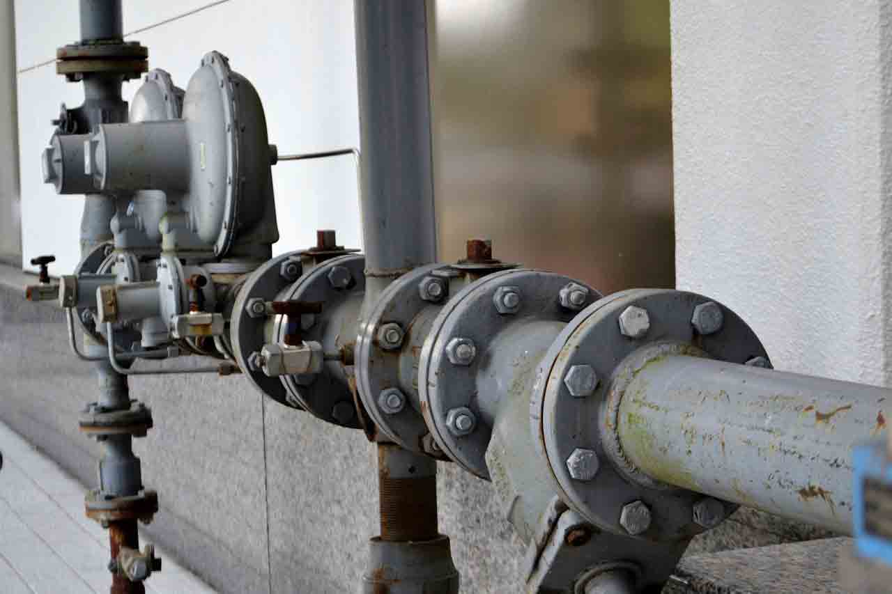
Valves in Pipe System Design.
The valve layout in a water distribution system is an important part of the pipe system design.
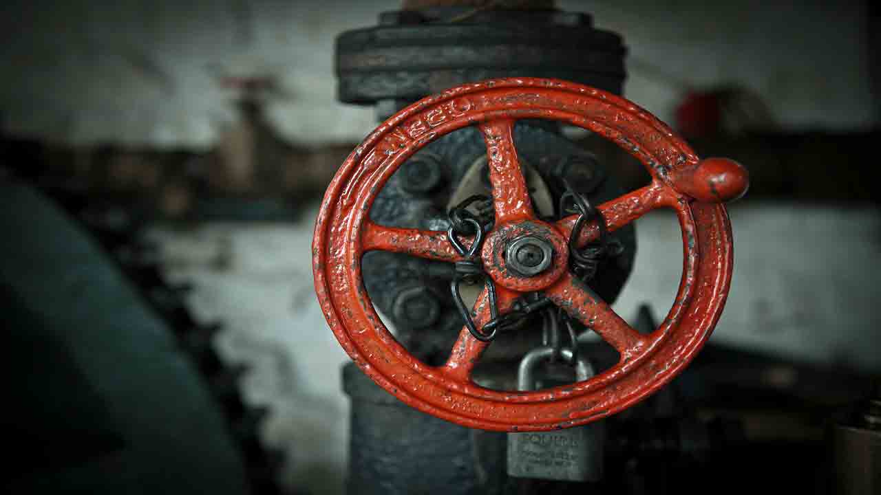
Types of Valves.
Numerous other types of valves are required, but by far the most common are gate valves, which should be not more than 1/4 mi apart.
A closer spacing is preferable in order to minimize the area cut off from water during repairs.
Air-relief valves should be provided at summits and drain valve: at low points.
Gate valves over 12 inches in size are usually placed in manholes to permit inspection and are provided with concrete supports to prevent settling.
Small valves are accessible from the street through cast-iron valve boxes in which a special wrench can be inserted.
Valve; can become inoperable because of corrosion or sediment accumulation and should be inspected at least once a year.
Standardized locations for gate valves (such as the northeast corner of an intersection) permit them to be found readily in emergencies.
Altitude valves to prevent the overflow of elevated tanks are usually designed to operate automatically.
Pressure regulating valves may be used to divide the distribution system into various pressure zones.
Fire Hydrants in Pipe System.
Fire hydrants should be not more than 500 ft apart to avoid excessive head loss in the fire hose. They are usually much closer in high-value districts.
Hydrants are preferably placed at intersections so that they can be used in all directions from the corner.
Types of Fire Hydrants.
There are several types of fire hydrants and many designs within each type.
Flush hydrants are located in pits below the ground surface. They are not recommended for regions of heavy snowfall.
Wall hydrants project from the wall of a building and are used extensively in commercial districts.
Post hydrants, which extend about 3 ft above the ground near the curb line, are most easily located.
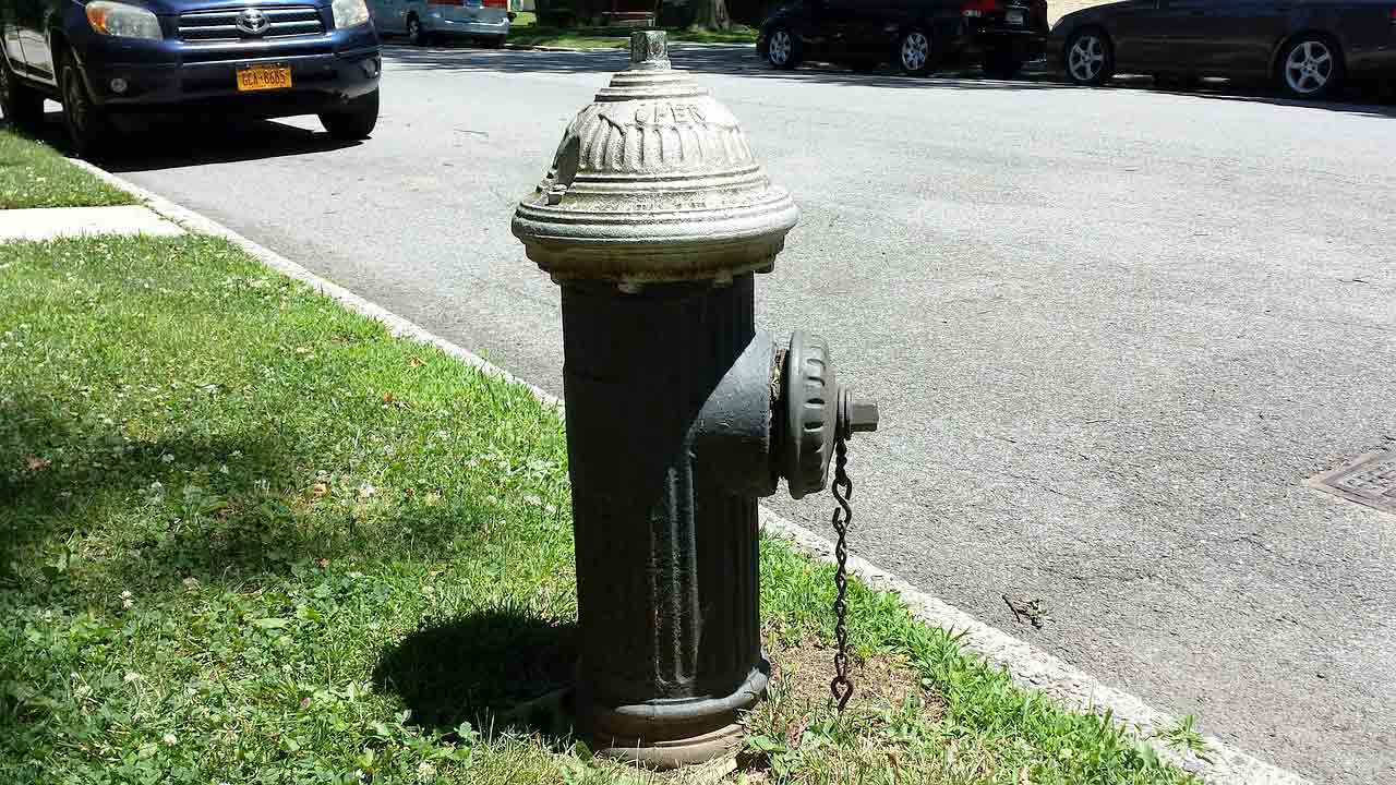
The hydrant is usually placed on a concrete block to eliminate settling and braced to resist the lateral forces of the flowing water.
Hydrants are provided with one or more 2-1/2 inches hose outlets and a 4 inches pumper connection if fire-department pumpers are to be used.
In cold climates, the valve is located below ground level so that the barrel contains no water except when in use.
A drain valve opens automatically when the hydrant valve is closed, to permit the escape of water after use and avoid damage by freezing.
This type of hydrant in pipe system can be designed in such a way that the valve is not likely to open if the hydrant is broken off by a car.
In warm climates, the hydrant barrel may contain water at all times, and an individual valve is provided for each outlet.
Thanks for Reading, Don’t Forget to share this article.
Read Also: Cement Manufacturing Process: What is Cement made of.